All machines produce heat when operating due to internal power losses. It is generally impractical to measure this heat rise with thermocouples or other temperature sensors, due to the majority of machines being sealed.
The winding construction is normally of copper, which has a known temperature coefficient. By measuring the change in resistance of the winding, the temperature rise can be calculated.
To accurately measure the resistance of the winding a Ohmmeter, or Micro-ohmmeter should be used. The meter should be a constant current machine, and should use the 4 wire measurement technique. By using a constant current any thermal emf issues will be removed, and the resistance value will be as accurate as possible.
Method
In order to get the best results use an Ohmmeter with a built in memory, and one with a timer module, this will allow for fully timed measurements to be taken, and at constant time intervals. The more accurate the measurement instrument, the higher the level of resolution in the temperature correction.
The winding is first measured with the machine at the ambient temperature and the resistance value Rcold noted.
The machine is then run at full load for a specified period to allow the temperature to stabilise.
The unit is switched off, and in the case of motors and generators, brought to rest and the winding resistance is again noted. It is important to take the first resistance reading as quickly as possible.
This is followed by readings at set time intervals with the values being recorded.
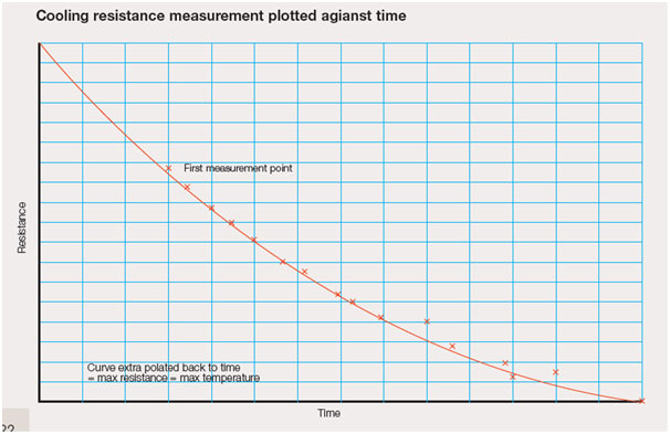
Readings can be held on the display and read before triggering the next reading without interrupting the measuring current. From the series of readings taken, it will be possible to draw a cooling curve and extrapolate back to the maximum resistance Rhot of the motor under full load. In this application, the temperature coefficient of the copper winding is used to measure the temperature changes.
Temperature rise T = (( Rhot – Rcold) / Rcold (TC))
Example: A motor field winding has a cold resistance of 1.3245Ω.
After running at full load for 8 hours the winding resistance is measured at 1.7654Ω. The temperature coefficient of the copper winding is 3930ppm/oC (0.3930%/oC)
T = ((1.7654 - 1.3245) / 1.3245 (0.003930) = 84.702 C
The above does not take into account any changes in ambient temperature which can have a significant effect on the resistance readings. If the measurements are taken on an Ohmmeter with Temperature correction all of the measured values will be corrected to 20 Deg C which will allow for a more accurate final result, as all of the ambient temperature changes will have be removed.
There are specialised Ohmmeters which have this feature built in.
Possible causes of error
1. It is important to make the first measurement as quickly as possible after the ma-chine is disconnected from its power source, and after all current ceases to flow, motors and generators should be brought to a stop condition.
WARNING damage is likely to occur to the ohmmeter if connected to the machine whilst current is still flowing.
2. Measurements should be made with a stable and continuous measurement cur-rent. DO NOT use auto ranging, switched DC current or pulse currents as this will give large measuring errors.
3. DO NOT switch off the measurement current to take each reading.
4. Make sure connections to the machine are clean and free from oxides. Use copper wire throughout and avoid using connection clips of different materials. The machine will get hot and any thermocouples created within the connections will generate large emfs.
5. WARNING Large distribution and power transformers should only be measured with “transformer testing ohmmeters which are designed specifically for this application. These ohmmeters incorporate safety circuits and measuring techniques designed for this application


